

WRT54G Hacking
Let’s get the basics out of the way. Even *opening* a Linksys WRT54G will void your warranty. If you’re not prepared for that, you can save yourself a lot of trouble by stop reading right here.
Also, these are just a record of *my* experiences with hacking a WRT54G; this isn’t designed to be a guide for others, and I won’t be held responsible for anything you may or may not do to yourself, others or anything else in the process of playing around with a WRT54G.
Most of what I’ve done here is as a result of reading Paul Asadorian and Larry Pesce’s fantastic book “Linksys WRT54G Ultimate Hacking”, and reading various websites including openwrt.org. As a result, what I’ve got listed here is quite concise, and assumes a lot of other knowledge that’s readily available from these other sources. What seemed to be lacking though is some of the pictures, schematics and diagrams for the version 2.2 board, so I’ve included them here.
If you’re interested, Paul and Larry have a great website and regular podcast available: www.pauldotcom.com
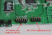
If you’re going to be playing around with the WRT54G, it’s worthwhile making yourself a JTAG cable. This plugs into JP2 on a version 2.2 board (provided you’ve installed some pin headers first!). The labels of JP1 and JP2 appear to be reversed on other versions, but the JTAG connection is easy enough to find; it’s the 5 x 2 connecter points at the front of the board. The serial port connector is the 6 x 2 points.
JTAG Cable
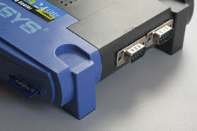
The WRT54G comes with two serial ports already built in; there just not connected externally. They’re also only TTL (ie 3.3 volt) so connecting them directly to a laptop/PC will pretty much smoke your router. Bummer.
But, all is not lost! The MAX232 IC is an ‘all in one’ chip that provides conversion between two TTL/RS232 ports.
If you want to do it the really easy way there are kits available via Compsys or even just on e-Bay. When converted to Australian dollars they come out to around $30, and at least a week of waiting.
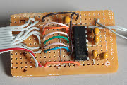
A much simpler (IMHO) way is to just go buy a MAX232 IC from the likes of Jaycar or Dick Smith, and also pick up the five capacitors, a piece of breadboard and a DB9 headshell while you’re there. You may even have some of this stuff kicking around; most unused serial cables with a DB9 connector can be put back to work with a swift clip of the side-cutters. If not though, I was able to pick up enough components to make three converters for the same $30.
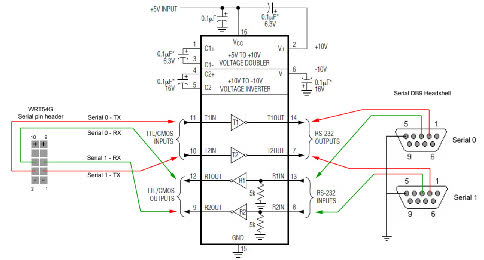
The following schematic shows how to wire up the WRT54G pin header to the MAX232 chip, as well as connecting the chip to the two DB9 serial connectors.
Serial Ports
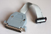
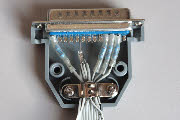
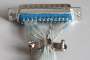
All that’s needed is a DB25 headshell, a pin header connector, a short length of ribbon cable (keep it at about 6 inches to prevent noise), and 4 x 100 Ohm resistors. A whole stack of useful information regarding the JTAG cable and its uses can be found at the OpenWrt.org Wiki. Oh, and a PC or laptop with a parallel port. This can be surprisingly hard to find.
Basically though to make one, just using the following wiring guide and the example pictures below.
JTAG Pin Parallel Port Pins 100 Ohm Resistor
3 2 Yes
5 13 Yes
7 4 Yes
9 3 Yes
2,4,6,8,10,12 18,19,20,21,22,23,24,25 No
Basically though to make one, just using the following wiring guide and the example pictures below.
JTAG Pin Parallel Port Pins 100 Ohm Resistor
3 2 Yes
5 13 Yes
7 4 Yes
9 3 Yes
2,4,6,8,10,12 18,19,20,21,22,23,24,25 No
This is really useful if you inadvertently, say, enter in the wrong NVRAM command, and find that upon reboot you’re left with a ‘brick’. Yes, let’s not speak of it again...
Oh, and of course you’ll need the extremely useful ‘Hairy Dairy Maid WRT54G Debrick Utility’. Can’t forget that one.
Oh, and of course you’ll need the extremely useful ‘Hairy Dairy Maid WRT54G Debrick Utility’. Can’t forget that one.
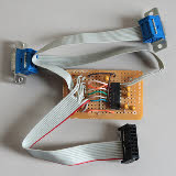
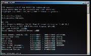
The following pictures then show the converter I put together, as well as a screen capture of the initial boot up sequence of the WRT54G, which is available via Serial interface 0. Note that only serial 0 provides terminal access.
The converter really is simple to put together, and the MAX232 chip is quite robust. I didn’t bother with any anti-static precautions, and if you look at the full sized version of the pictures, you’ll see the grinding dust on the capacitors from when I cut the board down and shaped it with a bench grinder.
SD Card
References / Reading
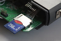
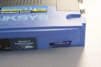
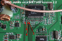
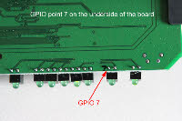
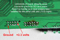
The ‘fun’ with the SD card hack for a WRT54G comes in finding the required GPIO points to solder to. This was largely undocumented for the version 2.2 board, so I’ve included it here for future reference. The next challenge is actually soldering to them! GPIO 3 and 4 (as can be seen in the photos) is extremely tight, and requires some very gentle soldering, and preferably the use of a magnifying glass. Checking with a multi-metre once you’re done to make sure there are no solder bridges is a good idea too.
The GPIO Utility (by mbm I think) is invaluable for being able to find and test the GPIO points. Once you’ve downloaded the utility, you can use the following script to toggle each GPIO point on/off every second, and then just start snooping around the board with a CRO or multi-meter:
while true
do
gpio enable 5
sleep 1
gpio disable 5
sleep 1
done
The above script will poll GPIO point 5, so changing ‘5’ for another GPIO point such as ‘3’ will then test for that point. This was the method I used to find points 3, 4 and 5 on the version 2.2 board.
I still seem to be having a problem with the driver for this hack, in so much as I’m able to see files on the SD card and can view small files, but larger amounts of data seems to lock up the router.


